1. Equipment Overview
The CO2 primary tower is a critical component in the purification section of a methanol plant. It is a sieve tray tower with a diameter of 2600 mm, which was commissioned in December 2007. During a maintenance shutdown in March 2009, multiple corrosion leaks were discovered at the welds of the gas inlet pipes. As shown in Figure 1, these leaks required immediate repair to prevent further damage and ensure safe operation. (1) Design pressure: 2.3 MPa; design temperature: 150°C; material: shift gas, K2CO3 solution, DETA solution; corrosion allowance: 1.0 mm; container classification: Class II. (2) Gas inlet pipe material: Cylinder body: 16MnR (lined with 0Cr18Ni9Ti), thickness: 20 mm; welded pipe: 0Cr18Ni9Ti, size: φ377 mm × 14 mm.
Figure 1
2. Cause Analysis
(1) Sampling analysis of the weld cracks revealed that, apart from the corroded areas, other parts showed no signs of corrosion and still had a clear metallic sheen. However, some sections exhibited serious loss of strength and plasticity, with cracks forming during cold bending—indicative of brittle fracture. (2) Based on the above findings, local corrosion leakage occurred at the welds of the gas inlet pipe. The primary cause was improper control of the welding process, leading to the formation of high-temperature delta ferrite and carbides in the weld joint. These microstructural features, under the influence of a corrosive medium, caused intergranular corrosion. The mechanism involves several factors. First, rapid cooling of the weld leads to insufficient diffusion of alloying elements, resulting in segregation. In regions where chromium and titanium (ferrite) are concentrated, and nickel and carbon are low, the formation of delta ferrite is promoted. This increases the amount of delta ferrite at room temperature, which has different physical and chemical properties compared to tempered sorbite. This weakens the intergranular bonding and reduces impact toughness. Second, increased heat input leads to more carbide precipitation. Since carbides are hard and brittle, they reduce the weld metal's toughness. The heat input is proportional to t8/5, which measures the time the weld remains between 500–800°C. Third, when carbides precipitate rather than dissolve in the crystal structure, the metal’s strength and corrosion resistance decrease. Chromium carbides, such as Cr23C6, tend to form along grain boundaries, creating chromium-depleted zones. These zones have reduced corrosion resistance, making them prone to intergranular corrosion in the presence of a corrosive medium.3. Process Measures to Prevent Intergranular Corrosion
(1) Minimize the heat input to the weld pool to reduce the time the weld spends in the sensitized temperature range, thereby reducing the risk of intergranular corrosion. (2) Use a proper welding technique, including concentrated heat sources, low heat input, and rapid cooling, to minimize carbide precipitation and avoid overheating of the joint structure. (3) During construction, use narrow welds, multi-pass welding, and control the interval between each weld. Allow the previous weld to cool to room temperature before proceeding. Avoid oscillating the welding gun, as this increases bath temperature and cooling time.4. Repair Measures
(1) Remove scale from the weld area where defects may occur and polish it to reveal a metallic luster. (2) Perform a 100% dye penetrant inspection on potentially defective areas to locate the exact position of the defect. (3) For identified cracks, use carbon arc gouging and an angle grinder to remove all defects. The groove shape after gouging is shown in Figure 2, with depth depending on crack severity. (4) After grinding, perform a 100% dye penetrant inspection. If the result meets Grade I standards per JB/T4730.5-2005, proceed with welding. (5) After completing the repair, conduct a 100% dye penetrant test again to confirm compliance with Grade I standards.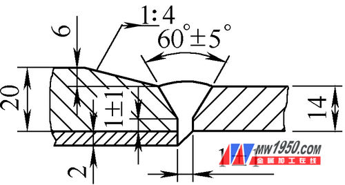
Figure 2
5. Pre-Weld Preparation
(1) Use electrode arc welding for the repair. (2) Ensure that welders are certified and qualified according to their “Welders’ Certificate†and possess the necessary qualifications. (3) Equipments: Two ZX7-400ST DC power supplies, carbon arc gouging tools, angle grinders, hammers, wire brushes, etc. (4) When using electrode arc welding, set the polarity to reverse DC. (5) Welding materials: 16MnR + 0Cr18Ni9Ti, with 0Cr18Ni9Ti welding consumables as shown in Table 1. Dry electrodes at the specified temperature and keep them warm at 100°C for use as needed.Table 1

6. Safety Measures
(1) All personnel entering the site must be certified, wear appropriate protective gear, follow analytical procedures, and comply with safety protocols. A detailed safety plan must be in place. (2) Ensure all electrical wiring follows standard practices, use automatic air switches and grounding protection, and place the welding machine in a safe location. (3) Ensure welding cables and ground wires are intact and not damaged. Do not use wire ropes as ground wires. Connect the ground wire directly to the workpiece during welding.7. Welding Process
(1) Before starting, adjust the welding parameters on a test plate and confirm the quality of the test weld. (2) After preparing the defective area, clean the weld joint with an angle grinder and grind the groove as shown in Figure 2. Maintain a groove angle of 60° ± 5°, ensuring the surface is flat and free of defects. Clean 30 mm on both sides of the weld, removing any contaminants like oil, rust, or slag. (3) Use the electrode arc welding parameters listed in Table 2.Table 2

Note: Reduce current by 10% when welding in vertical or overhead positions.
(4) Avoid striking the arc on the test surface or testing the current. Monitor the arc quality and ensure the molten pool is fully filled when closing the arc. (5) Use short-arc welding with small current and fast travel speed, without oscillation. Control the interlayer temperature below 60°C (the hand should not feel hot). (6) Immediately hammer the weld after completion to relieve stress, except for the first and cover layers. (7) Inspect the next weld bead. If any defects are found, remove them with a grinder and re-weld according to original specifications. Only authorized personnel may approve rework if it remains unqualified. (8) Clean the weld surface immediately after welding and inspect its appearance. (9) After passing the visual inspection, perform X-ray testing on the entire weld seam at 100% coverage. The result must meet Grade I standards per JB/T4730-2005.8. Conclusion
Thanks to accurate cause analysis and proper welding procedures, the repaired CO2 primary tower is operating smoothly. Over one year later, there have been no leaks in the gas inlet pipe, ensuring the device's safety, stability, and long-term performance.Small Solar Panels,Customized Solar Panel,Small Size Solar Panel,Small Size PV Module,Customized PV Module
Jiangyin Haoxuan Technology Co., Ltd. , https://www.haoxuan-tech.com