The 250km EMU axlebox is an important part of the bogie. It is connected with the bearing device and the movable joint of the wheelset, which transforms the rolling of the wheelset into the translation of the car body along the rail, and transmits each weight while bearing the weight of the train. The force of the direction.
The 200km EMU axlebox was imported from Kawasaki, Japan. In order to further localize the 200km EMU, the company began to develop the 250km axlebox in 2013.
The axle box body is an important part, and its machining precision is high. Through the tracking analysis of the processing and trial production process, the flexible production line is used to process the shaft box body to solve the quality problem in the processing process, and a practical and feasible processing scheme is formulated, which can ensure The machining accuracy of the axle box meets the design requirements, and the machining capacity and quality of the axle box body can be improved. The quality and efficiency are greatly improved to meet the production needs.
1. Processing equipment:
The shaft box flexible processing line consists of an information system, a processing system and a material handling system (see Figure 1).
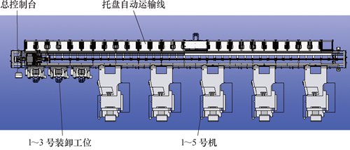
figure 1
The information system is the main console of the production line, mainly for processing program editing, job management, tool management, and so on.
The processing system consists of 5 NH63000DCGII host devices. The five devices are arranged in turn according to the No. 1 machine, No. 2 machine, No. 3 machine, No. 4 machine and No. 5 machine, and the No. 1 machine is equipped with a U-axis tool. Each machine has a tool capacity of 100, with on-line detection and tool breakage detection.
The material conveying system consists of a total of 48 pallet positions, 3 loading and unloading stations and 1 pallet automatic transport line for the upper and lower pallet racks. The axle box production line is equipped with 32 pallets for mounting workpieces according to production requirements. The material handling system sends the pallets to the pallet position, loading and unloading station and 5 equipment to be processed according to the operation schedule of the main console.
2. Processing characteristics:
The processing characteristics of the axle box body are as follows: the 1-axis box body is clamped twice by the first and second stations, and all the dimensions are processed. 2 According to the production requirements, multiple products can be processed in parallel. The 3-axis box production line can realize continuous work and no-man automatic operation when the machining tools of each process meet the requirements of use. 4 After setting the processing plan, plan the priority adjustment in the main console for the temporary expedited production plan, which can easily cope with the production emergency.
3. Product situation:
The material of the product is ZG25MnNi, which belongs to the casting parts. The mechanical properties of the axle box are high in impact resistance, tensile and ductility, but there are casting defects such as sand holes, hard spots, sand sanding and hard spots for welding. These defects are easy to damage the tool. Reduce the durability of the blade and affect the machining accuracy of the workpiece.
4. Process characteristics:
According to the company's supporting economic requirements, after the rough processing of the blank for the shaft box, the unilateral retention is 1.0~1.5mm. When processing on the flexible processing line of the axle box, according to the design requirements of the tooling, part of the rough processing is determined. For the process positioning dimensions, tolerances are specified.
5. Processing:
The shaft box to be processed is shown in Figure 2. The two-station clamping is used to complete all dimensional processing requirements.
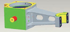
Figure 2 Axle box stereo view
(1) One station paperback. The shaft box is laid flat, and the inner hole after the rough processing is used, and the two-pin positioning clamping method (see Fig. 3) is used to complete the spring cylinder and the bottom surface, the clearing surface, the shaft temperature detector, and the time axis temperature sensor. Install the size of each part of the seat, the damper seat, the size of each part of the oil hole, and drill the tapped holes of each part of the station.
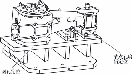
Figure 3 Schematic diagram of the flat clamp
(2) Two-station vertical installation. The 50mm cylinder with the spring face and the bottom plane and the node end are positioned to clamp the workpiece (see Figure 4). The hole diameter of the bearing hole and the dimensions of the end faces, the joint holes and the end faces are drilled, and the inside of the drill hole is chamfered, and the threaded holes of each part of the work are drilled.
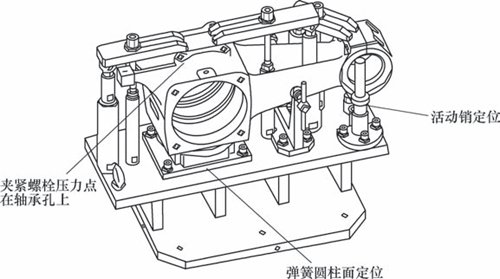
Figure 4 Schematic diagram of the fixture
6. Difficulties in processing:
(1) Timely shaft temperature sensor mounting seat processing: In order to ensure the safety of high-speed EMU driving, the temperature change of the axle box bearing device during operation is detected at any time, and the temperature of the axle box bearing device is too high to avoid the safety hazard of driving, 250km EMU The axle box body adds a time-axis temperature sensor device to the 200km EMU axle box body, and the time-axis shaft temperature sensor mount is designed.
The angle between the shaft temperature sensor mounting seat and the shaft housing bearing hole and the node hole center line is 35°, the mounting M2-6H threaded hole depth is 48mm, the thread effective length is 43mm, and the matching sensor bolt accuracy is 6g. The mating clearance is less than 0.02mm (see Figure 5). Because the center angle is 35°, the machining space is narrow. During the machining process of the numerical control equipment, the main shaft and the outer wall of the joint hole interfere with each other. Therefore, it is necessary to use an extended tool. However, the tool lengthens, the tool vibration during the milling process, and the surface roughness of the machined surface is out of tolerance. The screwing length is large, and it is difficult to ensure the matching precision. The selection of the face milling cutter and the tap cutter body is difficult for this process.
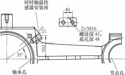
Figure 5 Schematic diagram of the shaft temperature sensor seat
(2) Machining of each part of the bearing hole: the end face of the bearing and the dimensions of the hole (φ235+0.046+0mm, φ230+0.044+0.015mm), high requirements on shape and position accuracy, roundness 0.02mm, cylindricity 0.02mm, vertical The degree is 0.02mm, the end face of the joint is perpendicular to the bearing end face of 0.05mm, and the vertical distance of the joint hole to the end face is 0.05mm. The design dimensions of the bearing holes are shown in Figure 6.
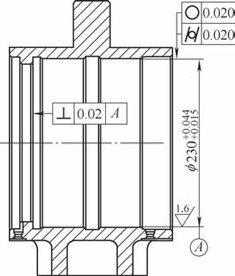
Image 6
To meet the machining accuracy requirements of the axle box, it requires advanced processing equipment, reasonable tooling, and the correct process. In the case of meeting various processing requirements, we must also take into account production efficiency, ensure production progress, and meet production needs.
Previous 1 2 Next
Ideal for windows with roller shutters
Completely pre-assembled, no assembly needed
Frame made of powder-coated aluminum
High quality fiberglass fabric
UV-resistant, washable, light and air permeable, natural insect protection with open window
Durable, stable structure, easy installing (Simply push in the guide bar of the roller shutter), EN13561-2015 certification.
Resistance to wind loads: Class 1
Operating effort: Class 2
Mechanical Endurance: Class 1
Resistance to corrosion: Class 2
As the professional Insect Screen supplier, we cooperated with consumer from all the world to settle the insect problem.
Sliding Insect Screen Without Strip
Sliding Insect Screen Without Strip,Screen Mesh,Flyscreen Curtain,Magnet Strip Door Screen
Huanghua Techo Building Material Co., Ltd. , http://www.insectsscreen.com