**Working Principle of Steam Flow Meter and Selection of Vortex Flowmeter**
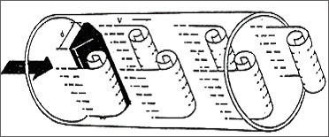
A steam flow meter operates based on the principle of vortex shedding. When a triangular column is placed in the fluid, it generates regular vortices alternately on both sides of the vortex generator. These vortices are known as Karman vortices. As shown in the image below, the vortices are arranged asymmetrically downstream of the vortex generator.
**Advantages of Vortex Flowmeters:**
1. A new generation of intelligent vortex flowmeters that offer high precision, strong anti-vibration capability, and excellent resistance to interference. They are ideal for measuring steam, gas, and liquid flows under various conditions.
2. The combination of the vortex flow sensor, display instrument, and compensation method forms a complete vortex flowmeter system. This device is a typical example of modern flow measurement technology.
3. The vortex flow sensor is designed using the Karman vortex principle and modern electronic technology. It features high reliability, excellent technical performance, good adaptability to different media, and versatility.
![]()
The **JT-LUGB series** of vortex flowmeters can accurately measure gases, liquids, and vapors across a wide range of flow rates without being affected by physical properties. It is not influenced by temperature or pressure, resistant to clogging, and suitable for high-temperature and high-pressure environments.
It is safe, explosion-proof, and ideal for harsh industrial settings. With no moving parts, no voids, and no wear or dirt accumulation, it requires minimal maintenance and has a long service life.
The flowmeter uses micro-power technology and can be battery-powered, allowing continuous operation for over two years. It features integrated voltage regulation compensation and electrically isolated current outputs with strong common-mode interference rejection.
The device displays both the instantaneous flow and totalized flow, eliminating the need to switch between displays. An anti-vibration probe helps reduce external vibration effects, while surface mount technology ensures compact design and high reliability.
With a split signal converter, the cable length can extend up to 10 meters. It offers a wide turndown ratio of 20:1, a reasonable overall structure, a broad dynamic measurement range, and low pressure loss. The body is made of stainless steel, making it suitable for corrosive media.
It provides on-site LCD display, pulse output, 4–20 mA output, or RS-485 communication, enabling integration with industrial automation systems.
**Vortex Flowmeter Sizing and Flow Range:**
| DN (mm) |
liquid |
gas |
steam |
| 20 |
0.8–10 |
5–40 |
8–80 |
| 25 |
1–12 |
7.2–60 |
10–120 |
| 32 |
1.5–20 |
12–100 |
15–200 |
| 40 |
2–30 |
18–150 |
20–300 |
| 50 |
3–50 |
30–300 |
30–450 |
| 65 |
6–80 |
50–420 |
60–800 |
| 80 |
10–130 |
70–600 |
100–1300 |
| 100 |
20–200 |
120–1000 |
200–2000 |
| 125 |
30–300 |
180–1500 |
300–3000 |
| 150 |
45–450 |
240–2000 |
450–4500 |
| 200 |
90–900 |
480–4000 |
900–9000 |
| 250 |
120–1200 |
700–8000 |
1200–12000 |
| 300 |
180–2000 |
900–10000 |
1600–16000 |
**Technical Parameters of Vortex Flowmeter:**
1. Measuring medium: gas, liquid, vapor
2. Caliber specifications: flange-mounted sizes such as 25, 32, 50, 80, 100
3. Flange connection types: 100, 150, 200
4. Flow measurement range: normal flow rate range Reynolds number 1.5×10â´ to 4×10â¶; gas 5–50 m/s; liquid 0.5–7 m/s
5. Measurement accuracy: 1.0 level or 1.5 level
6. Measured medium temperature: normal -25°C to 100°C; high temperature -25°C to 250°C
7. Output signal: pulse voltage (high 8–10V, low 0.7–1.3V), pulse duty cycle ~50%, transmission distance 100m
8. Pulse current remote transmission: 4–20 mA, transmission distance 1000m
9. Ambient temperature: -25°C to +55°C, humidity: 5–90% RH at 50°C
10. Material: stainless steel, aluminum alloy
11. Power supply: DC 24V or lithium battery 3.6V
12. Explosion-proof grade: intrinsic safety iaIIbT3-T6
13. Protection grade: IP65
**Applications of Vortex Flowmeters:**
Vortex flowmeters are widely used in industries like petrochemical, chemical, metallurgy, thermal power, textiles, and paper manufacturing for measuring superheated steam, saturated steam, compressed air, general gases (e.g., oxygen, nitrogen, hydrogen, natural gas), and liquids (e.g., water, gasoline, alcohol, benzene).
**Selection Guide for Vortex Flowmeters:**
| Spectrum |
Description |
| JTLUG |
|
Vortex Flowmeter |
| Detection |
B |
|
Piezoelectric sensor |
| Method |
E |
|
Capacitive sensor |
| Connection Method |
1 |
Fully tubular only |
Flange connection |
| 2 |
Fully tubular only |
Flange card type |
| 3 |
Insert type only |
Simple insertion type |
| 4 |
Insert type only |
Ball valve insertion type |
| Measuring Medium |
2 |
|
liquid |
| 3 |
gas |
| 4 |
steam |
| Nominal Diameter |
2 |
|
DN25 |
| ... |
... Unit: mm |
| 30 |
DN300 |
| Use Environment |
P |
|
normal type |
| B |
Explosion-proof |
| Output Signal |
1 |
Pulse output |
| 2 |
4–20mA current output, LCD display |
| 3 |
RS-485 communication |
| 4 |
Battery powered, no temperature/pressure compensation |
| 5 |
Integrated temperature/pressure compensation, 4–20mA output |
| 6 |
Temperature/pressure compensation, battery powered |
**Installation Diagram of Vortex Flowmeter:**
![]()
**Installation and Usage Guidelines:**
Proper installation of a vortex flowmeter requires sufficient straight pipe sections. Common conditions include:
| Pipe condition |
Upstream |
Downstream |
| Concentric shrink tube full open gate valve |
15D |
5D |
| 90° right angle elbow |
20D |
5D |
| Two 90° elbows in the same plane |
25D |
5D |
| Half open gate valve |
50D |
5D |
| Two 90° elbows in different planes |
40D |
5D |
| With rectifier bundle |
12D |
5D |
**Installation Conditions:**
1. The sensor should be installed on a pipe with the same diameter, either horizontally, vertically, or inclined (for liquid flow from bottom to top). Ensure that the upstream and downstream of the sensor have straight pipe sections of at least 15–20D and 5–10D, respectively.
2. The pipe near the sensor should be fully filled with the measured liquid.
3. Avoid installing the sensor on pipes with strong mechanical vibrations.
4. The inner diameter of the straight pipe section should be as close as possible to the sensor’s diameter. If not consistent, use a slightly larger pipe, ensuring an error ≤3% and not exceeding 5mm.
5. If the medium contains impurities, install a filter upstream of the sensor.
6. Protect the sensor from electromagnetic interference, cramped spaces, and hard-to-maintain locations.
**Natural Gas Flow Meter Price, Manufacturer, and Parameters**
When selecting a vortex flowmeter, consider the following parameters:
1. Pipe size
2. Measured medium name (note whether it is saturated or superheated steam)
3. Working pressure of the medium
4. Working temperature of the medium
5. Working flow rate of the medium
**Saturated Steam Density, Pressure, and Temperature Table:**
| Temperature °C |
Pressure kgf/m³ |
Density kg/m³ |
Temperature °C |
Pressure kgf/m³ |
Density kg/m³ |
| 120 |
2.0245 |
1.121 |
175 |
9.101 |
4.617 |
| 122 |
2.1561 |
1.189 |
176 |
9.317 |
4.721 |
| 124 |
2.2947 |
1.261 |
177 |
9.538 |
4.829 |
| 126 |
2.4404 |
1.336 |
178 |
9.763 |
4.936 |
| 128 |
2.5935 |
1.414 |
179 |
9.992 |
5.045 |
| 130 |
2.7544 |
1.496 |
180 |
10.225 |
5.157 |
| 132 |
2.9233 |
1.582 |
181 |
10.462 |
5.271 |
| 134 |
3.101 |
1.672 |
182 |
10.703 |
5.388 |
| 136 |
3.286 |
1.765 |
183 |
10.950 |
5.507 |
| 138 |
3.481 |
1.864 |
184 |
11.201 |
5.627 |
| 140 |
3.685 |
1.966 |
185 |
11.456 |
5.750 |
| 142 |
3.898 |
2.073 |
186 |
11.715 |
5.875 |
| 144 |
4.121 |
2.184 |
187 |
11.979 |
6.002 |
| 146 |
4.355 |
2.300 |
188 |
12.248 |
6.131 |
| 148 |
4.599 |
2.421 |
189 |
12.522 |
6.262 |
| 150 |
4.854 |
2.547 |
190 |
12.800 |
6.394 |
| 151 |
4.985 |
2.612 |
191 |
13.083 |
6.532 |
| 152 |
5.119 |
2.679 |
192 |
13.371 |
6.671 |
| 153 |
5.257 |
2.746 |
193 |
13.664 |
6.812 |
| 154 |
5.397 |
2.815 |
194 |
13.962 |
6.954 |
| 155 |
5.540 |
2.855 |
195 |
14.265 |
7.097 |
| 156 |
5.686 |
2.958 |
196 |
14.573 |
7.246 |
| 157 |
5.836 |
3.030 |
197 |
14.866 |
7.396 |
| 158 |
5.988 |
3.103 |
198 |
15.204 |
7.547 |
| 159 |
6.144 |
3.182 |
199 |
15.528 |
7.704 |
| 160 |
6.302 |
3.258 |
200 |
15.857 |
7.862 |
| 161 |
6.464 |
3.338 |
201 |
16.192 |
8.026 |
| 162 |
6.630 |
3.419 |
202 |
16.532 |
8.183 |
| 163 |
6.798 |
3.500 |
203 |
16.877 |
8.354 |
| 164 |
6.970 |
3.584 |
204 |
17.228 |
8.518 |
| 165 |
7.146 |
3.670 |
205 |
17.585 |
8.688 |
| 166 |
7.325 |
3.757 |
206 |
17.948 |
8.865 |
| 167 |
7.507 |
3.846 |
207 |
18.316 |
9.042 |
| 168 |
7.693 |
3.935 |
208 |
18.690 |
9.225 |
| 169 |
7.883 |
4.027 |
209 |
19.070 |
9.407 |
| 170 |
8.076 |
4.122 |
210 |
19.456 |
9.588 |
| 171 |
8.274 |
4.218 |
211 |
19.848 |
9.775 |
| 172 |
8.475 |
4.314 |
212 |
20.246 |
9.970 |
| 173 |
8.679 |
4.413 |
213 |
20.651 |
10.170 |
| 174 |
8.888 |
4.515 |
214 |
21.061 |
10.360 |
Flanged Bushing
ShaoXing Change Auto Synchronizer Ring Co.,Ltd , https://www.sxcjautoparts.com