1. Overview
During the charging and vibration process of a product, a 1Cr18Ni9Ti pipe joint experienced leakage at the fillet weld. After repairing the weld, the pressure test was resumed, and no further leakage was observed at that location. However, another leak occurred at the fillet weld of a different pipe joint and pipe A. The pipe joint in the combined conduit is made from 1Cr18Ni9Ti hexagonal steel, while the pipe itself is a 1Cr18Ni9Ti cold-drawn tube. The welding procedure included: matching the pipe and joint, pickling, welding, strength and airtight testing, passivation, cleaning, painting, and final inspection.2. Failure Analysis
(1) Macroscopic Observation: The macroscopic image of the combined conduit (Figure 1) shows cracks located at the fillet welds of the joints. These cracks are situated within the area marked by a black line, aligning with the weld bead. Visual inspection revealed no obvious macroscopic defects at the corner welds where cracks were present.

Figure 1: Macro photo of pipe joint fillet weld
(2) Chemical Composition Analysis: Samples were taken from both a 22 mm tube and a 6 mm pipe joint. The chemical compositions are listed in Table 1. All elements met the requirements of GB/T 1220-1992 for stainless steel materials used in the combined conduits.
Table 1: Chemical composition (mass fraction) of pipe joints and conduits (%)
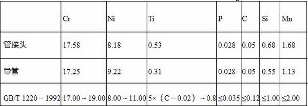
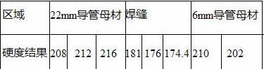
(3) Hardness Test: The pipe joint, fillet weld, and conduit were cut along a plane perpendicular to the 22 mm duct axis. Micro-hardness tests were conducted on the fillet weld and base metal, as shown in Table 2. The results indicate that the hardness of the weld zone is significantly lower than that of the base metal.
Table 2: Hardness test results of welds and base metals (HV)
(4) Metallographic Observation: A metallographic sample was prepared perpendicular to the crack surface. In the weld area adjacent to the 22 mm duct, a clear weld line can be seen, with no cracking observed nearby. The boundary between the fusion line and the outer surface aligns closely with the weld fillet. From the weld to the heat-affected zone and into the base metal, the microstructure changes continuously without any welding defects such as porosity or slag inclusions. On the left side of the weld line, the structure consists of dendritic ferrite distributed in an austenite matrix, while the right side shows austenite grains.

Figure 2: Weld area close to 22mm duct
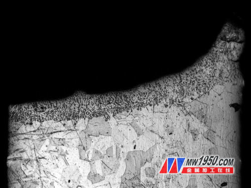
Figure 3: Crack propagation path and tissue near the crack

Figure 4: Fatigue strips in the fracture
The crack was found to originate in the weld area, approximately 130–160 μm from the fusion line, and runs parallel to it. The crack boundary coincides with the weld fillet. The surrounding microstructure contains dendritic ferrite in an austenite matrix.
(5) Fracture Observation: The crack was separated, and the fracture surface showed fatigue bands, indicating a fatigue failure. Some steps with significant height differences were also observed. The radial ridge lines extended from the outer surface toward the inner part of the catheter. Multiple crack sources were identified near the outer surface, suggesting multiple fatigue initiation points. The crack originated on the outer surface and propagated inward, showing a quasi-cleavage fracture surface. No defects such as voids or inclusions were found near the crack source.
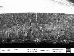

Figure 5: Topography of the fracture
3. Discussion
From the visual and fluorescent test results, it was determined that the crack formed at the fillet weld of the pipe and joint, aligning with the weld bead near the 22 mm pipe. The fracture morphology analysis revealed significant fatigue bands on the fracture surface, with strip widths of about 2 μm, confirming a fatigue-induced crack. The fracture surface exhibited large undulations, with the end region of the fatigue crack appearing fan-shaped. The center of the fan pointed toward the outer surface of the fracture. The fatigue crack source was located near the outer surface of the weld. Magnified observations revealed multiple fatigue sources on the outer surface, consistent with a normal fatigue fracture. No material or weld defects were found near the crack source. This indicates that the fatigue cracks initiated at the weld bead surface, which is typical under cyclic loading conditions. The chemical composition of the components met the required standards, and the hardness ranged between 202–216 HV. However, the weld zone had lower hardness, making it more prone to yielding under the same stress level. Microstructural analysis confirmed the absence of defects like pores or inclusions in the weld zone, indicating a normal weld structure. Cracks formed at the weld fillet and propagated along the weld, starting 130–160 μm from the fusion line. Fatigue cracks developed at the weakest areas of the weld, where the cross-section was smallest and hardness was lowest. During vibration, stress concentration occurred, leading to fatigue cracks in these regions. As vibration continued, the cracks expanded until they reached the inner surface of the weld, causing leakage.4. Conclusion
(1) Cracks were caused by fatigue failure.
(2) Fatigue cracks originated at the outer surface of the weld, with multiple sources.
(3) Fatigue cracking occurred at the weakest point of the weld (near the weld line), representing a normal fatigue fracture.
(4) Fatigue cracking resulted from stress concentration at the weld toe during vibration.
Ceramic Thrust Bearing,Tapered Roller Thrust Bearing,Axial Thrust Ball Bearing,Miniature
Yuyao Shuguang stainless steel bearing Co., LTD , https://www.shuguangbearing.com